
|
Shanghai Orinet Electronic & Technical Co.,Ltd
|
| Payment Terms: | T/T,L/C |
| Place of Origin: | Shanghai, China (Mainland) |
|
|
|
| Add to My Favorites | |
| HiSupplier Escrow |

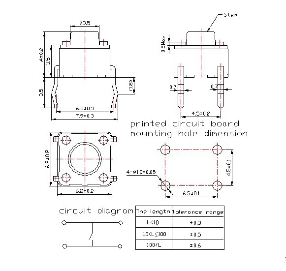
MODEL | DIM-h | STEM COLOR | ACTUATING FORCE(gf) | RETURN FORCE(gf) |
TS2A-043B | 4.3 | BLACK | 160±50 | 60 Min |
TS2A-060B | 6.0 | BLACK | 160±50 | 60 Min |

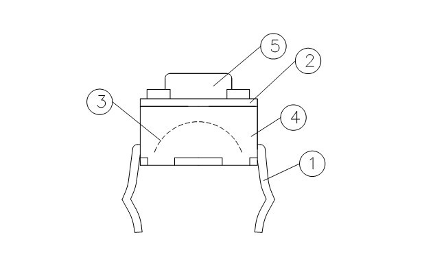
ITEM | COMPONETS | MATERIAL ARTICLE |
1 | TERMINAL | BRASS |
2 | FRAME | SPCC-SD |
3 | CONTACT | Phosphor bronze |
4 | HOUSING | PA66 |
5 | BUTTON | PA66/PC |
Item | Test Conditions | Requirements |
6.1.1. Contact Resistance | Applying a static load twice the actuating force to the center of the stem, measurements shall be made with a 1 kHz small-current contact resistance meter. Sample should be tested within 21 days after delievery. Package should not be broken. | Initially 50 m Ohm Max. |
6.1.2. Insulation Resistance | Measurements shall be made following application of DC 500 V potential across terminals and across terminals and frame for one minute. | 100 M Ohm Min. |
6.1.3. Dielectric with- standing voltage | AC 500V (50Hz or 60Hz) shall be applied across terminals and across terminals and frame for one minute. | No arcing or break down shall occur.Trip current<0.5mA |
Item | Test Conditions | Requirements |
6.2.1. Actuating Force | Placing the switch such that the direction of switch operation is vertical and then gradually increasing the load applied to the center of the stem, the maximum load required for the stem to come to a stop shall be measured. | 160± 50 g f |
6.2.2. Travel | Placing the switch such that the direction of switch operation is vertical and then applying a static load twice the actuating force to the center of the stem, the travel distance for the stem to come to a stop shall be measured. | 0.25 + 0.2/-0.1m m |
6.2.3. Return Force | The sample switch is installed such that the direction of switch operation is vertical and, upon depression of the stem in its center the whole travel distance, the force of the stem to return to its free position shall be measured. | 60 g f Min. |
6.2.4. Actuator Strength | To the press direction 10N until the stop for 5 sec. | Without damage of actuator.Function and action is in gear. |
Item | Test Conditions | Requirements |
6.3.1. Resistance to Low Temperatures | Following the test set forth below the sample shall be left in normal temperature and humidity conditions for one hour before measurements are made: (1)Temperature: -40±3°C (2) Time: 16 hours (3)Water drops shall be removed. | Item 6.1 Item 6.2.1 Item 6.2.2 |
6.3.2. Heat Resistance | Following the test set forth below the sample shall be left in normal temperature and humidity conditions for one hour before measurements are made: (1)Temperature: 85±2°C (2) Time: 96 hours | Item 6.1 Item 6.2.1 Item 6.2.2 |
6.3.3. Moisture Resistance | Following the test set forth below the sample shall be left in normal temperature and humidity conditions for one hour before measurements are made: (1) Temperature: 40±2°C (2)Relative humidity: 90 to 95% (3) Time: 96 hours (4)Water drops shall be removed. | Contact resistance: 200 m Ohm Max. Insulation resistance: 10 M Ohm Min. Item 6.1.3 Item 6.2.1 Item 6.2.2 |
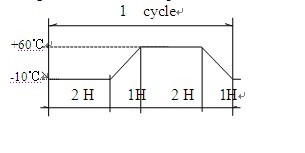
6.3.4. Temperature Cycling | Following five cycles of the temperature cycling test set forth below the sample shall be left in normal temperature and humidity conditions for one hour before measurements are made. During this test, water drops shall be removed.  | Item 6.1 Item 6.2.1 Item 6.2.2 |
Item | Test Conditions | Requirements |
6.4.1. Operating Life | Measurements shall be made following the test set forth below: (1)DC 5V 5mA resistive load (2)Rate of operation: 20 to 30 operations per min (3)Depression: Twice the actuating force (4)Cycles of operation: 10x104 cycles | Contact resistance: 100 m Ohm Max. Insulation resistance: 10 M Ohm Min. Actuating force: + 30 % or - 30 % of initial force Item 6.1.3 Item 6.2.2 |
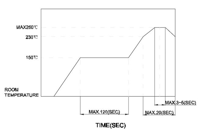
6.4.2 Solder-Ability | An hour later,the steam ageing.The soldering area of the terminal shall be immersed into molten solder at a temperature of 260±5°C for 2±0.5sec. | More then 90% of the dipping part shall be covered by solder. |
6.4.3 Soldering heat resistance | The soldering area of the terminal shall be immersed into molten solder at a temperature of 260±5°C for 5 sec. | There shall not be deforming in appearance |

ITEM | SUBSTANCE |
CARTON BOX | CORRUGATED PAPER |
PACKING CTN | CORRUGATED PAPER |
PLASTIC BAG | NORMAL PLASTIC |