|
Shanghai Orinet Electronic & Technical Co.,Ltd
|
| Payment Terms: | T/T,L/C |
| Place of Origin: | Shanghai, China (Mainland) |
|
|
|
| Add to My Favorites | |
| HiSupplier Escrow |

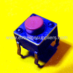
MODEL | DIM | STEM COLOR | ACTUATING FORCE(gf) | RETURN FORCE(gf) | LED |
TS2I-R | 7.2 | WHITE | 180±60 | 70 Min | Red |
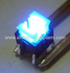
TS2I-U | 7.2 | WHITE | 180±60 | 70 Min | Blue |
TS2I-E | 7.2 | WHITE | 180±60 | 70 Min | Green |
TS2I-Y | 7.2 | WHITE | 180±60 | 70 Min | Yellow |
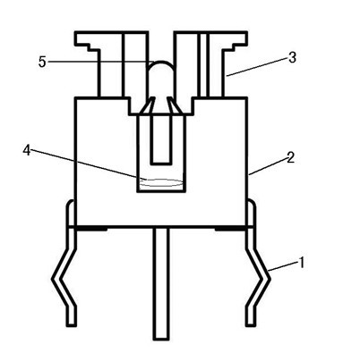
ITEM | COMPONETS | MATERIAL ARTICLE |
1 | TERMINAL | BRASS STRIP SILVER CLOTHED |
2 | HOUSING | PA66 |
3 | STEM | PA66 |
4 | CONTACT | STAINLESS STEEL |
5 | LED | CRISTAL CAP WITH COLOUR LIGHT |
Item | Test Conditions | Requirements |
6.1.1. Contact Resistance | Applying a static load twice the actuating force to the center of the stem, measurements shall be made with a 1 kHz small-current contact resistance meter. | 100 m Ohm Max. |
6.1.2. Insulation Resistance | Measurements shall be made following application of DC 100 V potential across terminals and across terminals and frame for one minute. | 100 M Ohm Min. |
6.1.3. Dielectric with- standing voltage | AC 250 V (50Hz or 60Hz) shall be applied across terminals and across terminals and frame for one minute. | There shall be no breakdown. |
6.1.4. Bounce | Lightly striking the center of the stem at a rate encountered in normal use (3 to 4 operations per sec.), bounce shall be tested at "ON" and "OFF". 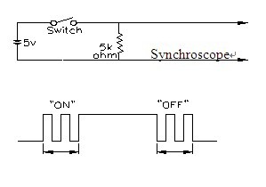 | 10 m sec Max. |
Item | Test Conditions | Requirements |
6.2.1. Actuating Force | Placing the switch such that the direction of switch operation is vertical and then gradually increasing the load applied to the center of the stem, the maximum load required for the stem to come to a stop shall be measured. | 180 ± 60 gf |
6.2.2. Travel | Placing the switch such that the direction of switch operation is vertical and then applying a static load twice the actuating force to the center of the stem, the travel distance for the stem to come to a stop shall be measured. | 0.25 ± 0.2 m m |
6.2.3. Stop Strength | Astatic load of 3 kgf shall be applied in the direction of stem operation for a period of 60 seconds. | No damage(Electrical and mechanical) |
6.2.4 Stem Strength | The maximum force to withstand a pull applied opposite to the direction of stem operation shall be measured. | 500 g f min |
Item | Test Conditions | Requirements |
6.3.1. Resistance to Low Temperatures | Following the test set forth below the sample shall be left in normal temperature and humidity conditions for one hour before measurements are made: (1)Temperature: -30±2°C (2) Time: 96 hours (3)Water drops shall be removed. | Item 6.1 Item 6.2.1 Item 6.2.2 |
6.3.2. Heat Resistance | Following the test set forth below the sample shall be left in normal temperature and humidity conditions for one hour before measurements are made: (1)Temperature: 80±2°C (2) Time: 96 hours | Item 6.1 Item 6.2.1 Item 6.2.2 |
6.3.3. Moisture Resistance | Following the test set forth below the sample shall be left in normal temperature and humidity conditions for one hour before measurements are made: (1) Temperature: 60±2°C (2)Relative humidity: 90 to 95% (3) Time: 96 hours (4)Water drops shall be removed. | Contact resistance: 200 m Ohm Max. . Item 6.1.3 Item 6.1.4 Item 6.2.1 Item 6.2.2 |
6.3.4. Temperature Cycling | Following five cycles of the temperature cycling test set forth below the sample shall be left in normal temperature and humidity conditions for one hour before measurements are made. During this test, water drops shall be removed. 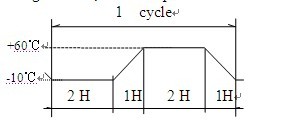 | Item 6.1 Item 6.2.1 Item 6.2.2 |
Item | Test Conditions | Requirements |
6.4.1. Operating Life | Measurements shall be made following the test set forth below: (1)DC 12V 50mA resistive load (2)Rate of operation: 40 to 60operations per minute (3)Depression: Twice the actuating force (4)Cycles of operation: 100,000 cycles | Contact resistance: 200 m Ohm Max. Bounce: 20 m sec Max. Actuating force: + 30 % or - 30 % of initial force Item 6.1.3 Item 6.2.2 |
6.4.2. Vibration Resistance | Measurements shall be made following the test set forth below: (1)Amplitude:1.5 mm (2)Cycle of sweep: 10 -55 -10 Hz in one minute, (3)Sweep method:Logarithmic frequency sweep rate. (4)Time:Each direction 2 hours(Total 6 hours) | Item 6.1 Item 6.2.1 Item 6.2.2 |
6.4.3. Impact Shock Resistance | Measurements shall be made following the test set forth below: (1)Acceleration:80g (2)Cycles of test:3 cycles each in 6 directions, for a total of 18 cycles | Item 6.1 Item 6.2.1 Item 6.2.2 |
Item | Soldering condition |
7.1.1 Soldering Temperature | 260℃ Max. |
7.1.2 Duration of Solder Immersion | 5 sec. Max. |
7.1.3 Allowable Frequency of Soldering process | 2 times Max. |
7.2 Other precautions (1) Following the soldering process, do not try to clean the switch with a solvent or the like. (2) Safeguard the switch assembly against flux penetration from its topside. (3) Please have the products keep in close status and the storage time is 90 days guaranty after delivering the goods at most. | |
Shanghai Orinet Electronic & Technical Co.,Ltd [China (Mainland)]
Business Type:Manufacturer, Trading Company, Agent, Distributor/Wholesaler, Service
City: Shanghai
Province/State: Shanghai
Country/Region: China (Mainland)